Robot arm
A palletising robot made from flat steel. Three linear actuators drive it, and nothing slides. Every joint turns.
- Context
- SDU · Integrated Design 3 · 2025
- Built from
- 1.5 mm steel · rivets · axles · 3D print
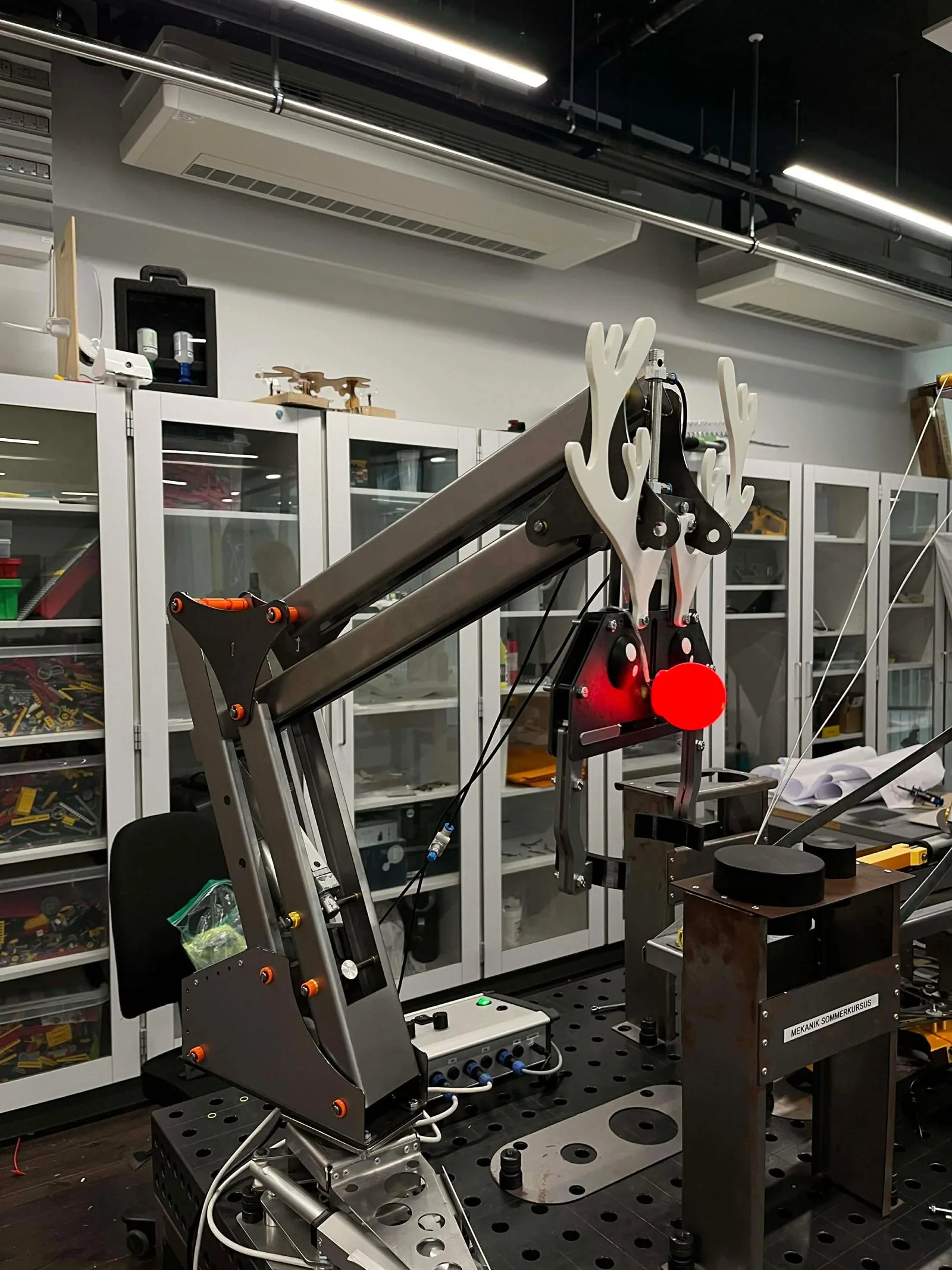
Move two parts from a low platform to a high one. As fast as you can.
We were handed a base that turns about 80°, driven by a linear actuator. The rest was ours: two more degrees of freedom, each on its own linear actuator, and a pneumatic gripper. All in laser-cut steel, bent by hand. On the last day, every group raced the two parts against the clock.
An actuator pushes in a straight line. We wanted every joint to turn.
So no actuator slides a part along. Each one pushes on a short lever behind the pivot, so a short stroke turns into a long swing at the tip. That gives the arm its reach. One actuator, one joint. The arm moves like an arm.
The gripper has to face the parts the same way wherever the arm is. Two parallel links do that on their own. No extra motor, nothing to control.
No report to write. So we built, and tried, and built again.
We found the geometry with cardboard and LEGO, not calculations. The cardboard arm went straight onto the real base, next to the real platforms. If it couldn’t reach both, it was wrong, and we could see it in seconds.
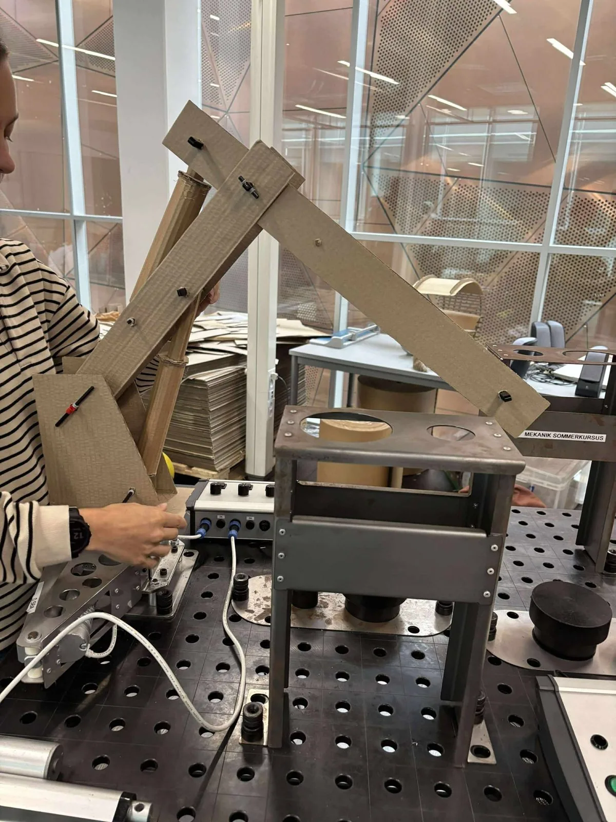
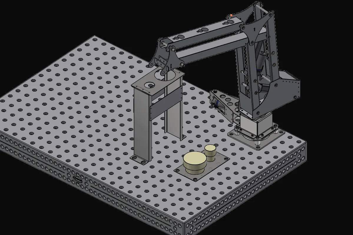
Every part starts as a flat sheet.
The laser cuts it, we bend it by hand, rivets hold it. So we drew the arm as sheet metal from the start. The first version was flat plates full of oval holes. The built arm folds each link into a closed profile: the same sheet, much stiffer.
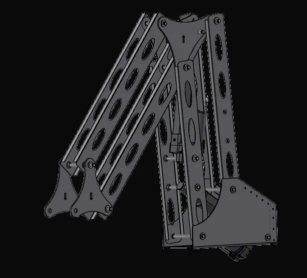
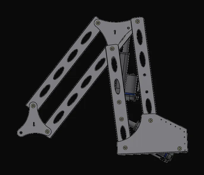
Laser-cut steel, pop rivets, axles and 3D prints. Nothing else.
1.5 mm steel, cut and bent in the SDU workshop. Rivets join the sheets, steel axles carry the joints, and 3D prints fill in where sheet metal isn’t the right answer.
Three actuators. Three controls. One person at the box.
There’s no program. A control box drives each actuator on its own, and the operator plans the path in their head: down, grip, up, swing, down, release. Because each control turns one joint, what you do with your hand is what you see the arm do.
The best advice came from the workshop, not the screen.
SDU has machinists in the workshop with years of experience in exactly this: cutting, bending and joining steel. Talking to them early saved us from mistakes we would only have found at the bending machine. Now I go to the people who make things before I commit to a design.
- People
- Use the experience around you. A five-minute question to a skilled craftsperson beats a day of guessing.
- CAD
- Drawing in sheet metal from the start, so what’s on screen is what the laser cuts and the machine bends.
- Rapid prototyping
- Cardboard and LEGO answer geometry questions in minutes. Build it, hold it up to the real thing, change it.